What software and files do I need to operate my deformable mirror?
There are three software items required to properly operate your deformable mirror; including two configuration files, specific to the device you have, that should be copied to their respective folders within the Boston Micromachines software folder.
DMSDK
The Boston Micromachines Deformable Mirror Software Development Kit (DMSDK) provides a common interface to all BMC products. It allows users to write one code base that can be used with any product. Command line and graphical applications are provided for demonstration of the DMSDK and hardware functionality. A C API is provided for versatile development of high performance applications.
Adaptive Optics (AO) Software Development Kit (SDK) available as an upgrade. Find out more about our AOSDK.
DM profile
A configuration file that is matched to a unique DM-Driver combination. A profile contains information such as deformable mirror array size, actuator mapping, voltage limits, the driver PC interface type, and other settings. Profile file names contain the serial number of the deformable mirror device to which they apply. Contact us if you have any questions regarding your DM profile.
Flat map file
A type of Command Map that drives the deformable mirror surface to a plane that is parallel to the silicon wafer base. This file is optional and useful for calibration and alignment of your optical component.
Flat maps for deformable mirrors are established by Boston Micromachines and are unique and custom to only that DM-Driver combination. Boston Micromachines typically supplies a flat map with each deformable mirror at 50% deflection for use in establishing a mirror surface for optical alignment and calibration. Other flat map files are also available — please inquire for more details.
How do deformable mirror actuators work?
The concept behind MEMS deformable mirrors is pretty simple. This simple design enables them to be fast and efficient devices.
There is an electrode layer, an actuator layer and a mirror layer.
You ground the actuator layer. When a voltage is put on an electrode, the actuator layer above it is attracted and it pulls the mirror layer down. Voila! A deformable mirror. The motion for every device is pretty much the same.
The interesting thing about deformable mirrors is that there are many ways that you can fabricate the mirror layer and therefore many types of mirrors that you can make. If you want a big, smooth surface, simply make the mirror layer continuous across the entire mirror. If you want each actuator to control a small region that is independent of the others, a segmented mirror is for you. And, if you want larger segments which are controlled by multiple actuators, just divide the surface up the way you want to and you can have separate mirrors that can be controlled with a number of actuators, like our Hex-TTP (Tip, tilt, piston) version that we offer.
In the past, versions of various sizes and segments has been created. And, if you want something more esoteric, we’re happy to entertain your ideas.
Some of the common configurations that Boston Micromachines has created for applications from astronomy to laser communication:
What does my deformable mirror surface layout look like?
MEMS deformable mirrors are typically fabricated in a cartesian layout format. This is simple to lay out and stays consistent from the smallest to the largest sizes.
Within the cartesian layout, there are two types of mirrors:
Continuous Deformable Mirror
A Deformable Mirror where the reflective mirror surface extends continuously (without any breaks) over the entire actuator array. In Continuous DMs, actuator arrays can be linear, square grid, or other type of pattern.
Typical configurations (actuator maps):
Multi Deformable Mirror
Multi-C Deformable Mirror
Kilo-C Deformable Mirror
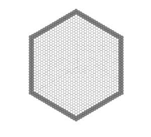
Hex-TTP Deformable Mirror
Breaking up the surface into hexagonal segments, with three actuators controlling each, enables tip-tilt-piston (TTP) functionality and provides the user with the ability to achieve precise angular and phase control with each optical segment. Typical sizes of mirrors are shown below.
Hex-111 Deformable Mirror
Hex-1011 Deformable Mirror
Hex-3K Deformable Mirror
Boston Micromachines has published a whitepaper on the architecture. It can be accessed on our Hex Class Deformable Mirrors page.
How big is my deformable mirror and how much of the mirror surface is actually useful?
Deformable mirror surfaces are classified by Boston Micromachines in three different ways: Full Aperture, Active Aperture and Recommended Optical Aperture. Below we will describe these different apertures for our standard continuous surface deformable mirrors.
Full Aperture (FA)
The largest circular region that fits within the deformable mirror’s reflective surface. The Full Aperture is what you see when looking directly at the deformable mirror, and is also known as the Unpowered Surface Figure. As it is not entirely controllable, the Full Aperture is typically not used, but is useful to know if the application calls for overfilling the useful area.
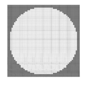
Full Aperture For Continuous Deformable Mirrors
Continuous deformable mirrors have two or more rows of inactive actuators outside of the controllable actuators. The reflective area extends to the outermost inactive actuators.
The diameter of the Full Aperture is [(actuators across) + 3] x (pitch)
Full Aperture (red circle) overlaid on the actuator map
Surface scan of the Full Aperture
Active Aperture (AA)
The largest circular region that fits within the displaceable controllable area of the DM surface. The Active Aperture is a circle inscribed within the outer controllable actuators. The area within the Active Aperture is displaceable but not fully controllable at the edges, because the controllable outer actuators are coupled to actuators further out that cannot be controlled.
The diameter of the Active Aperture is ([actuators across] -1) x [pitch]
Active Aperture (red circle) overlaid on the actuator map
Surface scan of the flattened Active Aperture
Recommended Optical Aperture (OA)
The largest circular region that fits within the displaceable and fully controllable area of the deformable mirror surface.
For continuous DMs, the Recommended Optical Aperture is a circle inscribed within the next actuator in from the outer controllable actuators. Like the Active Aperture, the area within the Recommended Optical Aperture is displaceable but is also fully controllable at the edges, because the controllable outer actuators are coupled to actuators further out that can also be controlled.
The diameter of the Recommended Optical Aperture is ([actuators across] -3) x [pitch]
Recommended Optical Aperture (red circle) overlaid on the actuator map
Surface scan of the flattened Recommended Optical Aperture
How fast are deformable mirrors?
There are a few areas that need to be addressed with respect to the speed of a MEMS based deformable mirror. The best way to do this is by separating out the different forms of latency/delay in the system.
Electronics latency
We define the latency of our electronics as the time between the first command written to the last DAC (digital to analog converter) updated. In the case of our USB drivers, the data is sent over the USB protocol in 125us packets which leads to the calculation of 8kHz frame rate.
For our X/S-Driver architectures, much higher frame rates of up to 400kHz are possible, depending on the number of actuators addressed. This is the first source of delay with deformable mirror systems.
Amplifier slew rate
The next delay in the system involves the slew rate of our amplifiers. For most of our devices, we utilize a custom Supertex amplifier that slews at 5.1V/us. Therefore, this is completely dependent on the size of the step taken for a given command. This should be added to the electronics latency when evaluating the system. For our X-Driver architecture, we utilize improved amplifiers that yield a slew rate of 11.6V/us, which is what makes the higher speeds possible.
Actuator Mechanical response
The final consideration when calculating the system latency is the mechanical response time of the DM. For some users, this is not a consideration as they are more concerned with sending commands as quickly as possible and are not worried about the position of the DM. However, for others, this is important since they would like to detect a settled wavefront for analysis in the control loop. The mechanical response is summarized in the documents below for each of our DM architectures.
Surface response
Finally, the entire surface of the mirror must be taken into account when considering how fast your system can go. The major concern here is air damping. While individual actuators can move with sub-100 microsecond speed, as the air trapped under the surface moves around, it can affect the settling time of the entire surface. The surface response time for continuous deformable mirrors is on the order of 150 to 300 microseconds, depending on the stroke and spacing of the actuators.
How stable is my deformable mirror?
Boston Micromachines deformable mirrors exhibit highly stable operation with no hysteresis and no measurable drift, down to the sub-nanometer level. Our MEMS based deformable mirrors have been extensively tested for various parameters, including stability. We currently have a 4096 actuator count deformable mirror integrated into the Gemini Planetary Imager (GPI). Before its installation, MEMS stability was tested by applying a flattened shape to the device with successive wavefront measurements taken every 38 seconds, for 60 iterations. Short term stability was measured over 9 minute intervals, within the long term stability test.
The shorter time scale is comparable to typical closed loop operation times. Stability was measured to be 0.08 nm RMS phase by replacing the MEMS with a flat mirror. Average long term stability of the MEMS was measured as 0.16 nm RMS phase. On the shorter time scale, the system is more stable with an average RMS deviation of 0.13 nm RMS phase for the MEMS, and 0.07 nm RMS phase for the flat mirror. Previous tests had indicated less stability because of errors produced by the MEMS drive electronics that have since been corrected. The figure below is a curve of growth showing that most of the actuators are quite stable. Of the 500 actuators tested, there was 97% stability of better than 0.16 nm RMS over 38 minutes.
Curve of growth for stability data (standard deviation of surface over 60 measurements taken in 38 minutes)
MEMS based deformable mirrors are the foundation of a class of deformable mirrors providing compact devices scalable to thousands of actuators and capable of correcting high order aberrations with high precision and repeatability, while exhibiting no hysteresis. Various tests and projects have proven the level of precision obtainable using MEMS deformable mirrors.
Ground-based high-contrast imaging telescopes can be used for extrasolar giant planet detection. Such an application has demanding wavefront control requirements, two orders of magnitude more precise than standard adaptive optics systems. A research laboratory in California, USA performed tests to demonstrate that this can be achieved with a 1024 MEMS deformable mirror. The mirror surface was flattened to a residual wavefront error of 0.54 nm RMS, within the range of controllable spatial frequencies which are typically on the order of 10-30nm. The tests proved that the level of closed loop performance without any additional improvements meets the precision and accuracy requirements for a high-contrast giant-planet imager, qualifying MEMS technology for such an instrument. You can read more about the tests conducted and the results obtained in the referenced paper below.
At Boston Micromachines, we offer an upgrade to further improve your mirror hardware, making your deformable mirror even more precise. The high resolution upgrade for the Kilo-Driver/S-Driver architecture enables control of our deformable mirror hardware with increased resolution. The Kilo-Driver has an increase from 14-bit to 16-bit step resolution, and the faster S-Driver has an increase from 12-bit to 14-bit step resolution over the full range of mirror deflection. Research scientists at NASA utilized the Kilo-Driver upgrade to 16-bit resolution when they designed new space telescope optics for coronagraphs. This design does more than just detect exoplanets, it also takes photos of them. To take the photos, a new technology called phase-induced amplitude apodization (PIAA) is used to develop an extremely powerful coronagraph. Click here to learn more about this exciting technology.
What about inter-actuator coupling and influence function?
Powered actuators have an influence on their neighboring actuators in continuous surface deformable mirrors.
The actual displacement is determined by:
The magnitude of the command sent to the actuator.
An offset caused by inter-actuator coupling.
The magnitude of this offset is related to the stroke, the actuator spacing, and the relative displacement of adjacent actuators.
As the mirror surface that is directly controlled by an individual actuator is attached to the mirror surfaces over adjacent actuators, the position of those adjacent surfaces negates the full effect of the actuator. The closer the surrounding surfaces are to the actuator’s driven position the greater the coupling.
While quantifying inter-actuator coupling becomes complicated when the adjacent mirror surfaces are at differing positions, it is relatively straightforward when the adjacent surfaces are un-powered.
Influence function
The BMC deformable mirror architecture allows for local deformation of the mirror membrane with an influence function from 11-25% depending on the specific device design. Influence function, defined as the ratio of the deflection induced on a neighbor of a powered actuator and the maximum deflection of the powered actuator, with all other actuators at half bias, for the three different deformable mirror actuator types is shown below.
These profile measurements of the deformable mirror surfaces at half bias with an actuator pulled down and poked up show the influence functions of these devices to be 15%, 13%, and 22% for the 1.5, 3.5, and 5.5μm stroke deformable mirror actuator types respectively.
Deformable mirror actuators at half bias
with single actuators at 0 and maximum command, respectively
Influence function of a 1.5 μm stroke deformable mirror
Influence function of a 3.5 μm stroke deformable mirror
Influence function of a 5.5 μm stroke deformable mirror
Deflection and pitch
For BMC deformable mirrors, deflection is the distance moved by an actuator from its unpowered state. Due to the architecture, actuators are pulled down when voltage is applied, which is why deflection (height) is represented below in negative values. On the other hand, pitch is the distance between each actuator within a deformable mirror.
Deformable mirror with every other row actuated at maximum command
Maximum inter-actuator stroke of a 1.5 μm stroke deformable mirror
Maximum inter-actuator stroke of a 3.5 μm stroke deformable mirror
Maximum inter-actuator stroke of a 5.5 μm stroke deformable mirror
Can my deformable mirror operate using open loop control?
Boston Micromachines offers open loop calibration for your deformable mirror as an upgrade. This allows you to precisely control the position of your mirror, without the need for a feedback sensor and control algorithm. We provide calibration files specific to your device that allow you to control your deformable mirror without feedback. This is useful in a variety of applications, such as high-resolution microscopy and laser communication.
Due to the method used for creating calibration files, currently we offer open loop calibration for deformable mirrors with up to 492 actuators. Contact us if you would like to purchase the open loop calibration upgrade for your deformable mirror, or if you have any questions about the process.
Open loop calibration file
A calibration file contains the exact voltages necessary for a series of specific actuator deflections over the range of 0 to 1.0 (full stroke). For continuous deformable mirrors, at each deflection the position of the surrounding 8 actuators is also recorded.
Calibration files are used in open loop applications where there is no feedback on actuator deflection. For a specific mirror shape, i.e., an array of desired actuator deflections, the calibration file contains the actuator voltages necessary to drive the deformable mirror to that shape by taking into account both the position of each actuator, and the influence of the surrounding actuators. For deflections between those in the calibration file, the necessary voltages can be interpolated.
The Calibration File is created by Boston Micromachines through interferometric analysis of a single representative actuator and is valid for only that DM-Driver combination. Calibration file names contain the serial number of the DM device to which they apply and have file name extension .mat; these files are stored in a folder within Program Files\Boston Micromachines\Calibration. As installed, the Calibration folder contains a few generic calibration files for demonstrative purposes.
Can MEMS deformable mirrors be used in space and cryogenic environments?
Boston Micromachines deformable mirrors (DM) can operate in cryogenic conditions, as well as environments lacking an atmosphere, such as space. Small and large DM models have been tested to operate in such conditions.
Space Projects
Planet Imaging Concept Testbed Using a Rocket Experiment (PICTURE)
A NASA sounding rocket for high-contrast imaging with a visible nulling coronagraph, the PICTURE payload has made two suborbital attempts to observe the warm dust disk inferred around Epsilon Eridani. The rocket was designed to significantly advance the science and technology supporting exoplanet research, the PICTURE-B mission of the Lowell Center for Space Science and Technology, at the University of Massachusetts Lowell successfully launched and returned to Earth in November 2015. The DM used in the rocket was a continuous surface Kilo-DM, with 1024 actuators, and 1.5 µm stroke. The observations from the experiment demonstrated the first operation and measurement of a DM for high-contrast imaging in space with reflected light.¹
Image courtesy of E. Douglas, University of Massachusetts Lowell
Deformable Mirror Demonstration Mission (DeMi)
Boston Micromachines was recently part of the DeMi mission, lead by MIT STAR Lab, in a collaboration effort with Aurora Flight Sciences. The mission used a CubeSat, a class of miniaturized satellites, with our MEMS based DM installed in it to validate and demonstrate wavefront control for a precision of less than 100 nm RMS to be used in space for high-contrast astronomical imaging. The CubeSat was retired in March 2022 after a successful two-year long mission. Click here to read more about the DeMi mission.
Artist’s rendition of the DeMi CubeSat in orbit
Our DMs are also baselined for two of the biggest upcoming NASA space-based telescope project concepts:
Habitable Exoplanet Observatory (HabEx)
HabEx is a concept for a space telescope mission which will directly image planetary systems around Sun-like stars for exoplanet discovery. One of the instruments in HabEx will be a coronagraph, fitted with a high-actuator count MEMS based DM. Click here to learn more about the instrument.
HabEx telescope flying in formation with the Starshade (NASA)
Large Ultraviolet Optical Infrared Surveyor (LUVOIR)
LUVOIR is also a concept mission for a highly capable, multi-wavelength space observatory. The mission will encompass a broad range of science and discovery, from the formation of the galaxy and its evolution, to remote sensing of solar systems and exoplanet discovery. Click here to check out the ambitious LUVOIR mission.
LUVOIR-A observatory with a 15 m telescope (NASA GSF)
Environmental Testing
All Boston Micromachines DM model membranes qualify for operation in cryogenic environment. Tests have been performed on the MEMS DM component as well as chip carriers and interface hardware based on three factors; temperature, vibration, and environmental conditions. Groups such as Japan Aerospace Exploration Agency (JAXA) and Jet Propulsion Laboratory (JPL) have performed various tests to prove the eligibility. Contact us if you would like to use your DM in a cryogenic environment and have specific questions.
Temperature
In the most recent temperature testing performed by JAXA, it was found that a custom Kilo-DM was successfully operated at 5 Kelvin. The performance of the DM was qualitatively consistent with the principle of electro-static DMs. There was no hysteresis and an operating repeatability of 2.6 nm RMS was found. In addition, the DM remained durable over three cooling cycles.
Color maps of deflection at various command voltages at 295 K/1 atm, 295 K/0 atm, and 5 K/0 atm conditions (starting from the left column)
Vibration
There have been a few vibration and acoustic tests performed on Boston Micromachines DMs. In the most recent test, performed by JPL in 2021, it was found that high-actuator count DMs are robust to flight-level random vibrations. MEMS DMs can achieve high-contrast imaging performance even after flight-relevant environmental testing. The vibration/acoustic tests pave the way for Technology Readiness Level (TRL) 6 and demonstrate that our MEMS DMs can be used for future space missions.
2048-actuator DM vibration test performance conducted by Boston Micromachines
Environmental
JAXA and JPL have performed tests on rapid pumping and radiation exposure, respectively. The rapid pumping test showed that the DM experienced no noticeable effects as there were no significant changes found during inspection. Radiation exposure test was performed on two groups with five DM actuators each, all located on a single device. Deflection data from the test proved no significant effects, on either group, due to radiation².
How much laser power can my deformable mirror withstand?
Standard Device Power Handling Experience
Below are tables which contain select conditions that have been recorded by customers using our deformable mirrors. Please contact Boston Micromachines for more information and any other data that we may have regarding the use of our mirrors in higher-power and longer wavelength conditions.
Continuous Facesheet Mirror
Energy (mJ/cm²)
Power (W/cm²)
Pulse Width
Wavelength (nm)
Size (mm)
Effect
N/A
20.8
CW
532
3.5
Correctable deformation
N/A
200.0
CW
1550
Unknown
Rippling
N/A
6.0
CW
532
Unknown
None
700
35.0
20 ns
1064
1
None
Hex Mirror
Energy (mJ/cm²)
Power (W/cm²)
Pulse Width
Wavelength (nm)
Size (mm)
Effect
N/A
50.0
CW
690nm
Unknown
None
What is the minimum step size of my deformable mirror?
When it comes to mirror step size, our mirrors behave as analog devices. Therefore, the step size is completely dependent upon the resolution and stability of the driver. With that in mind, our mirrors are delivered with two architectures of control electronics. These electronics have two types of digital-to-analog (DAC) scales. As an example, we will consider a deformable mirror system with a safe operating voltage of 210 V and our standard electronic driver resolution which is built on a 14-bit architecture.
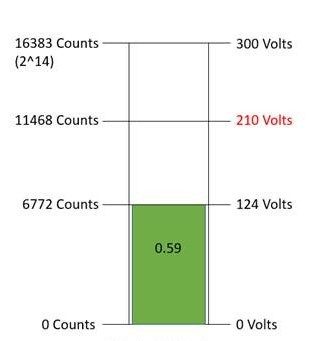
Kilo-/S-/Multi-Driver
For these electronic drivers, the DAC range is not changed — full scale is 0 to 300 V. The high voltage (HV) power supply is decreased, so that the HV adapter never outputs more than 210 V. The diagram below is a visual description of this DAC scale.
Kilo-/S-/Multi-Driver DAC scale for a required output of 210 V
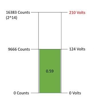
X-Driver
The X-Driver’s Vr (voltage reference adjustment) and Vp (HV output rail adjustment) are adjusted so that all the DAC bits scale to the maximum safe operating voltage for the deformable mirror system, i.e. 210 V for this example.
X-Driver DAC scale for a required output of 210 V
Deflection vs. Voltage
Other than the DAC scales described above, a deformable mirror system’s precision is also dependent on its deflection/voltage relationship. Our MEMS based deformable mirrors have, approximately, a quartic relationship between the voltage applied and its corresponding deflection. For example, The graph below is a deflection curve for a system with 210 V safe operating voltage.
Deflection vs. ratio of maximum safe operating voltage applied
Generally between 20% and 90% of the maximum deflection, a deformable mirror system has a linear relationship between its deflection and the voltage applied. When operating within this region, you can easily approximate your deformable mirror’s deflection based on the voltage. In this example, the deformable mirror has a maximum stroke of 3764 nm when the electronic driver outputs 210 V. In DM Shapes, our GUI application, you can input command values down to the thousandths, so the minimum step size in this case would be 3.764 nm of deflection (i.e. pulling an actuator down by 3.764 nm). However, if you use our SDK to interface with your deformable mirror, you can obtain higher precision via smaller step size. For an electronic driver built on the 14-bit architecture, the smallest step size obtainable is 0.000061 BMC command value (ratio of maximum voltage) which corresponds to motion of less than 1 nm for most deformable mirror models.
Have more questions?
Boston Micromachines Corporation can help you understand deformable mirror technology better. Contact us today.